SuperSnappy.txt
From ReplayResources
Jump to navigationJump to search
Super Snappy hardware/programming docs
text included from supersnapshot.org
 http://style64.org/snappy |
Please check the text for credits - no edits below this line
Super Snappy hardware/programming docs
======================================

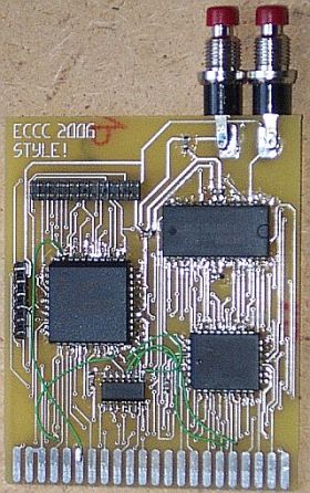
This document describes the hardware for the new Super Snapshot V5 compatible
cartridge designed by Adrian Gonzalez.  The latest revision of this doc should
be available at http://supersnapshot.org/docs/supersnappy.txt

Revisions
---------
2006/10/09: Added memory maps.  Added note about freeze during REU transfer.
2006/10/07: First draft.  Basic Hardware description.

===============================================================================

Introduction
------------

The Super Snapshot series of cartridges is one the most popular lines of freezer
carts in the North American C-64 scene.  The last cartridge in the series, Super
Snapshot V5 (SSV5), has a 64KB eprom and 8K of Static RAM.  A reset button and a
32K SRAM chip replacement are offered as options.  The ROM contains one of the
largest collections of useful (and not so useful) utilities ever seen in a
freezer cartridge.  As of the time of this writing, SSV5 is currently still
being produced and sold, with no changes or improvements to its ROM over the
past 16 (or so) years.

The need for an improved Super Snapshot was fueled by the availability of Retro
Replay, an improved Action Replay V freezer cartridge that sports an Amiga
'clock port', and its eventual serial port and ethernet add-ons.


Hardware description
--------------------

The main goal of the project was to provide updated hardware while retaining
SSV5 software compatibility.  The new and improved hardware consists of a 512KB
FlashROM chip, a 128KB static RAM Chip, a 22 pin Amiga clock port, and the glue
logic to make it all work.

The freezer has been improved over the original SSV5.  The freezer state machine
waits for three consecutive write cycles (stack push of program counter and
status register), whereas the original SSV5 hardware would just count three
write cycles, consecutive or not, which could end up enabling the freeze memory
map sooner, possibly crashing the computer.  The current hardware does not
monitor the DMA line on the cartridge port though, so freezing during a REU to
C64 transfer will most likely cause a crash (the freeze state machine will see
three consecutive write cycles and map SSROM in).


Snapshot Registers
------------------

SSV5 had a single, write-only register up at $dexx, mirrored across the entire
256-byte page.  The unused bits have been assigned to the address lines required
by the bigger 512KB FlashROM available in the new hardware.  The new hardware
has an additional register for controlling the clockport and disabling writes to
flashrom.  Both registers are still write-only!  Reading from $de00/de01 will
read from the corresponding address in FlashROM, not the contents of the
registers.  The registers are laid out as follows:

$DE00 Register:  This is the only register available in the original SSv5,
mirrored throughout de00-deff.  In the new hardware it is only available at
$de00 (and partially $de01).

Bit 0:  Controls the GAME line on the cart port
        0: GAME=0
        1: GAME=1
Bit 1:  Controls the EXROM line on the cart port (INVERTED!)
        0: EXROM=1
        1: EXROM=0
Bit 2:  Snapshot ROM Address line 14 (SA14)
Bit 3:  Snapshot memory/register enable (see description below)
Bit 4:  Snapshot ROM Address line 15 (SA15)
Bit 5:  Snapshot ROM Address line 16 (SA16)  -- Available but unused in SSv5
Bit 6:  Snapshot ROM Address line 17 (SA17)  -- Not available in original SSv5
Bit 7:  Snapshot ROM Address line 18 (SA18)  -- Not available in original SSv5


$DE01 Register:  The new control bits are unused in the orignal hardware, and
only available at $de01 in the new hardware.  The lower bits act the same as
$de00 to maintain software compatibility.

Bit 0:  Mirror from $de00 register (GAME control)
Bit 1:  Mirror from $de00 register (!EXROM control)
Bit 2:  Mirror from $de00 register (SA14)
Bit 3:  Mirror from $de00 register (reg/mem enable)
Bit 4:  Mirror from $de00 register (SA15)
Bit 5:  Extended control bit enable (see note 1)
        0: ignores values stored to bits 6/7
        1: control bits 6/7 active
Bit 6:  Clockport state restore bit
        0: no effect
        1: restore clockport enable/disable to its state before last freeze
        (see notes 2 and 3!)
Bit 7:  Clockport enable bit
        0: disable clockport
        1: enable clockport (see note 3!)


Note 1:  An extended control bit enable was used because the original SSv5 roms
sometimes write 0's to the top bits of $de01, which would have the undesired
side effect of disabling the clockport, for example.

Note 2:  Since the SS register is write-only, an alternate means to restore the
clock port to its pre-freeze state was needed (clock port is automatically
disabled on freeze, to maintain software compatibility with SSv5 ROMs).

Note 3:  Setting bits 5, 6 and 7 to 1 is a write-once combination that disables
FlashROM writes until next reset.  This combination was chosen because otherwise
there would have been some ambiguity (should this combination enable the clock
port, or restore it to it's pre-freeze state?).  Clock port state is unaffected
when setting FlashROM write-disable.


Memory Maps
-----------

Understanding how bits 0, 1 and 3 of the snapshot register control the C64's
memory map is crucial to understanding how the cartridge works.  Bits 0 and 1
control the GAME and EXROM lines, which are used to map portions of cartridge
RAM/ROM to certain areas of the C64's address space.  Bit 3 behaves like a
snapshot register/memory enable/disable, with some exceptions.  The best way to
explain how the cartridge works is to list the different possible memory maps
that can be achieved by setting the Snapshot register at $de00.  The following
memory maps assume $01 is set to its default value of $37.

$DE00 SS Register:
xxxx0x00 - SSDISABLE=0, EXROM=1, GAME=0: Ultimax RAM Mode
	0000-0fff: 4K of C64 RAM
	1000-7fff: empty
	8000-9fff: 8K of SSRAM
	a000-cfff: empty
	d000-dfff: 4K i/o (SSROM at $dexx) (see note 4)
	e000-ffff: 8K of SSROM
	This mode is the only way to access SSRAM.  Note that C64 RAM between
	$1000-7fff and $a000-cfff is completely GONE.  Code to be executed must
	be located somewhere below $1000, in SSRAM at $8000-9fff or in SSROM at
	$dexx or $e000-ffff.

xxxx0x01 - SSDISABLE=0, EXROM=1, GAME=1: Standard C64 memory map, SS Enabled
	$de00-deff: SSROM (see note 1)
	Standard C64 memory map otherwise

xxxx0x10 - SSDISABLE=0, EXROM=0, GAME=0: 16KB SSRom mapped in to $8000
	0000-7fff: 32K of C64 RAM
	8000-bfff: 16K of SSROM
	c000-cfff: 4K of C64 RAM
	d000-dfff: 4K i/o (SSROM at $dexx) (see Note 4)
	e000-ffff: 8KB kernal ROM
	This is your usual 16KB ROM cartridge memory map, plus SSROM at $dexx.
	Reads from $8000-bfff come from SSROM, writes to $8000-bfff go through to
	C64 RAM.

xxxx0x11 - SSDISABLE=0, EXROM=0, GAME=1:  8KB SSRom mapped in to $8000
	0000-7fff: 32K of C64 RAM
	8000-9fff: 8K of SSROM
	a000-bfff: 8K of Basic ROM
	c000-cfff: 4K of C64 RAM
	d000-dfff: 4K i/o (SSROM at $dexx) (see Note 4)
	e000-ffff: 8KB kernal ROM
	This is your usual 8KB ROM cartridge memory map, plus SSROM at $dexx.
	Reads from $8000-9fff come from SSROM, writes to $8000-9fff go through to
	C64 RAM.  This mode	is probably not used by the current SS ROM.

xxxx1x00 - SSDISABLE=1, EXROM=1, GAME=0: Ultimax Flash Mode (NEW MODE!)
	0000-0fff: 4K of C64 RAM
	1000-7fff: empty
	8000-9fff: 8K of SSROM
	a000-cfff: empty
	d000-dfff: 4K i/o (SSROM at $dexx) (see note 4)
	e000-ffff: 8K of SSROM
	This mode is NOT VALID in the original SSV5.  It will enable ultimax mode
	and disable the SS Register, so the only way to get back is to reset or
	power-cycle your C64.  In the new hardware, the SS Registers remain
	active (this is one of the exceptions where SSDISABLE=1 but the SS
	Register is not disabled).
	This mode can be used to write to or erase any part FlashROM, as long as
	writing to FlashROM has not been disabled by writing %111xxxxx to $de01.
     This setting was the obvious choice to add a
	flash mode, because it sets ultimax (needed for writes to go through to
	external ROM/RAM), and because it's invalid in the original SSV5, so
	compatibility issues are avoided.

xxxx1x01 - SSDISABLE=1, EXROM=1, GAME=1: Standard C64 memory map, SS Disabled
     SS completely gone from the C64's memory map.  The only way to access the
     cartridge is by using the freeze button.

Note 4:  The $dexx i/o area is mostly used by SS to store small routines that bridge the
gap between the standard C64 memory map and the extended features available in
the SS ROM.  The area of SS ROM mapped to $de00 depends on what the snapshot register
address bits are set to.  For example, using the standard C64 memory map with
SS Enabled (SS Reg = xxxx 0x01), you would get SSROM from 01e00-01eff mapped at
the $de00-deff area.  Address lines A13 and below are controlled by the CPU,
resulting in the following mappings:

     SS $de00 Register
     0000 0001: SSROM $01exx at C64's $dexx
     0000 0101: SSROM $05exx at C64's $dexx
     0001 0001: SSROM $09exx at C64's $dexx
     0001 0101: SSROM $0dexx at C64's $dexx
     0010 0001: SSROM $11exx at C64's $dexx
     ...
     1111 0101: SSROM $7dexx at c64's $dexx


